I spent another four or five hours today working on the car. Once again I was stymied by not being able to find a couple parts I needed and had some minor issues with getting things soldered properly, but I did manage to get a bunch of little things done on the car.
A few days ago I picked up the battery for the car. I had been debating between an Optima yellow top and an Optima red top battery. I ended up going with the red top because its warranty was three times longer than the yellow. To avoid the problems I had early on with the 911, I also bought a battery tender. (And yes, I am aware I talked about this in my last post…)
First things first today, I decided I wanted to drop the battery in the car. It was in the way, and where better to store it than in the car.
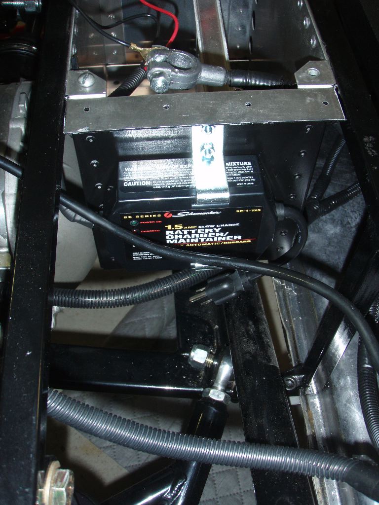
Last post I mentioned how I mounted the fuel filter bracket on the passenger side of the battery box. Following along with the use of the battery box for mounting space in the rear of the car, I decided to mount the battery tender on it as well, only on the drivers side. This is a good spot for it — its inboard pretty far and is well in from the wheels so, although its weatherproof, it’ll be less likely to get wet or hit by something kicked up by the wheels. It also keeps the cord to plug the car in out of the way. Odds are I’ll need to pull a wheel off or at least jack it up to plug the car in, but I think that will be okay.
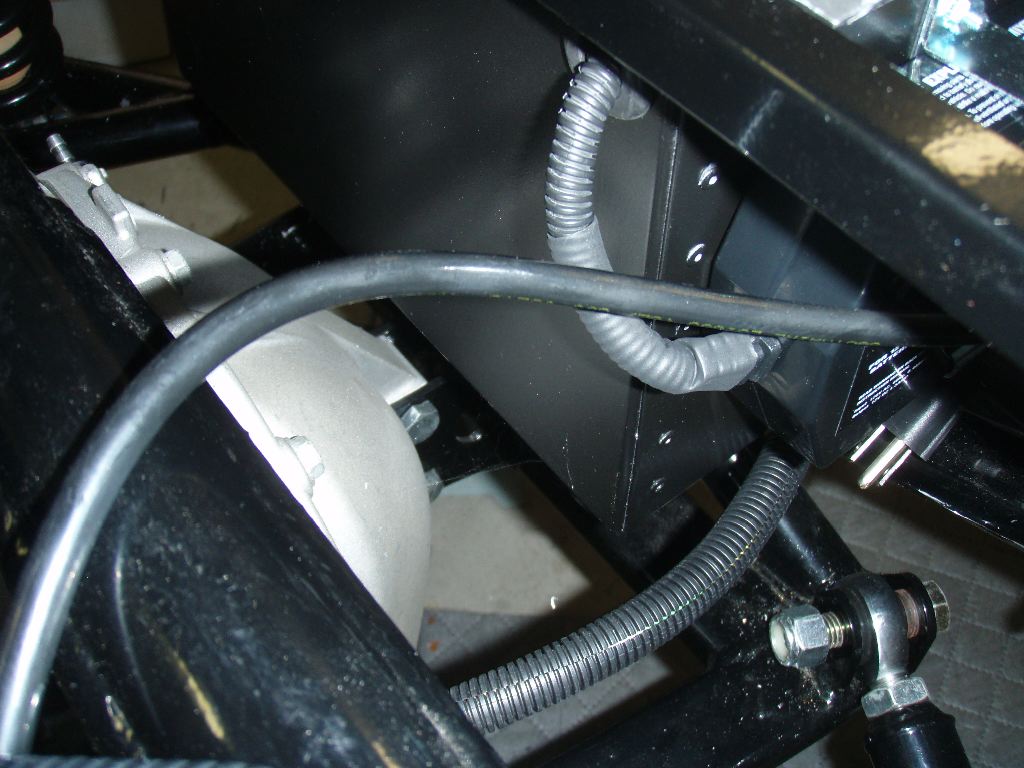
The battery leads were bare wires, so I used some split loom to protect them. A large heat shrink tube both holds it in place as well as binds it to the strain relief on the tender itself. The wires go through a grommet into the battery box.
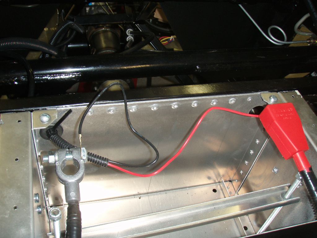
Inside the battery box, the two leads go to the battery cable clamps.
I also decided to redo some of the power wiring in the Digital Guard Dawg harness I had worked on last weekend. The wires were undersized for the power they were likely to carry. I replaced them with 10 gauge wiring.
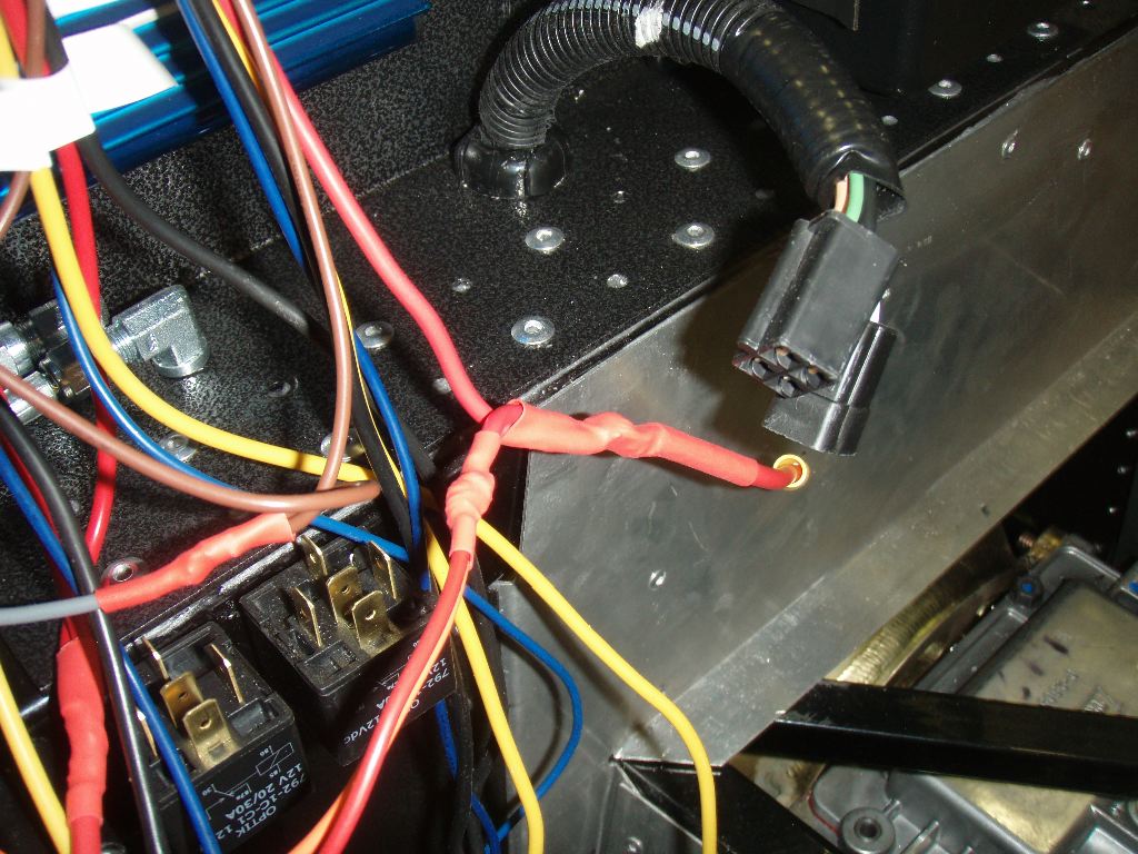
Unfortunately, I had issue with my 30 watt soldering iron getting two 10 gauge wires and an 8 gauge wire hot enough to solder them together securely. Instead I crimped connectors onto the end of them and figured I’d get a single post power distribution block, which would be handy anyway to give me a place I can tap some power behind the dash. Unfortunately I couldn’t find one.
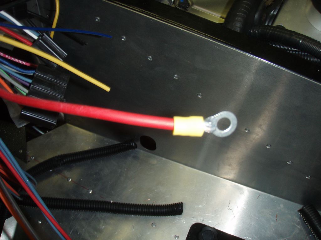
I’m still not sure how I’m going to deal with this. I can buy a 100 watt soldering iron (which frankly would be a good idea) and just solder them, or I can keep looking for an insulated terminal I can connect them together on.
On the other side of the power relays, I have a similar problem. I’d rather not solder the power wires for the starter, run and accessory states directly to the car’s harness but I can’t find 10 gauge crimp on insulated connectors. Autozone and Pep Boys have spots where they should be and don’t have them in stock.
At this point I decided to drop the battery into the car. As a tip, don’t pinch a finger between a heavy battery and an immovable battery box. It hurts.
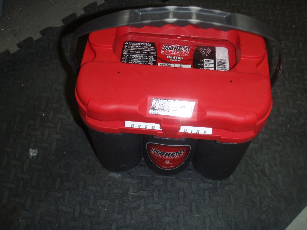
The battery box is designed for this battery. I got lucky and guessed which side of the Optima was + and which was – correctly, so the wires were on the correct side of the box.
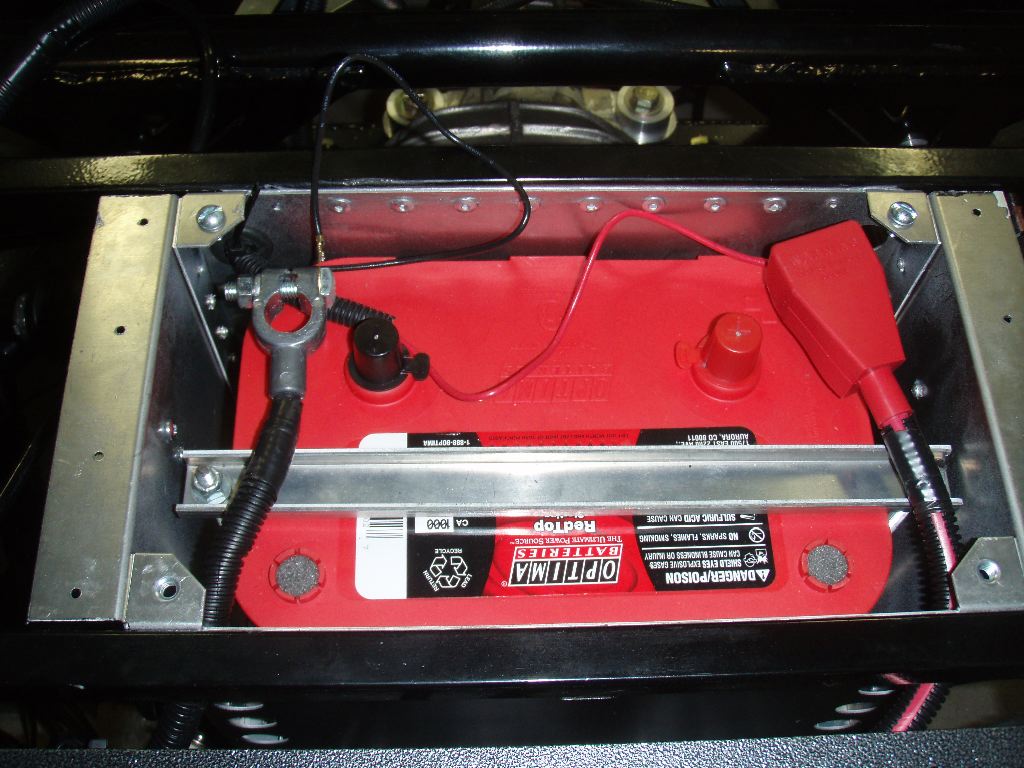
I did connect up the battery, with the power switch to the car disconnected, and nothing burst into flames. I think I’m going to replace the cable running to the alternator because I’d like something more flexible, but at least there was no poof of smoke from the alternator or anything when I applied power to the car. I didn’t flip the power switch on, however, as I think the odds are there are a lot of shorted wires in the harness right now.
A quick fix I also took care of was getting the Digital Guard Dawg controller mounted. Last week I mentioned that the mounting tab broke on it. The controller is designed to be mounted with a screw or with zip-ties. (There are channels on the side of it to hold onto a zip tie.) I decided to just drill two more holes in the aluminum bracket behind the dash and use a zip-tie.
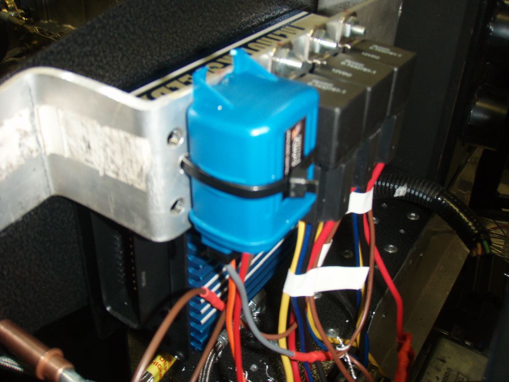
The last thing I did, as part of cleaning up the wiring harness, was install the add-on fuse block. This gives me four circuits I can add, two of which I need for the headlights.
The first step was drilling the rivet holes and getting the mount I had fabricated a few months ago riveted to the frame in the driver’s footbox. (Fabricated may be too strong of a word — its a piece of aluminum stock with five holes drilled in it…)
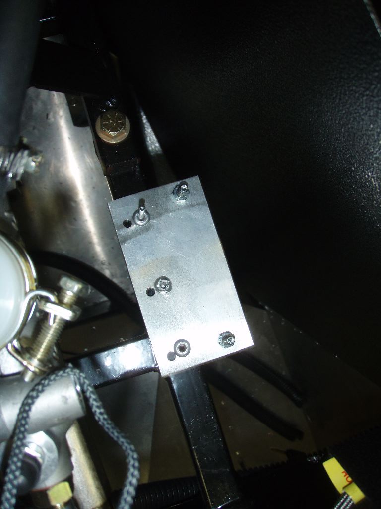
Unfortunately the rivet closest to the front of the footbox is in a spot I can’t pull with my hand riveter. I need one that can rivet on-end. I’ll either find one I can buy or borrow, or just leave that rivet out. It seems to be holding okay with two.
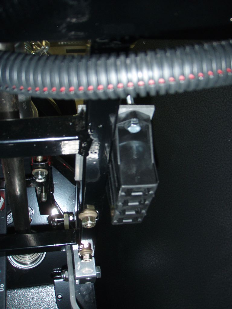
The fuse block itself is tucket up in the top of the footbox above the driver’s knee.
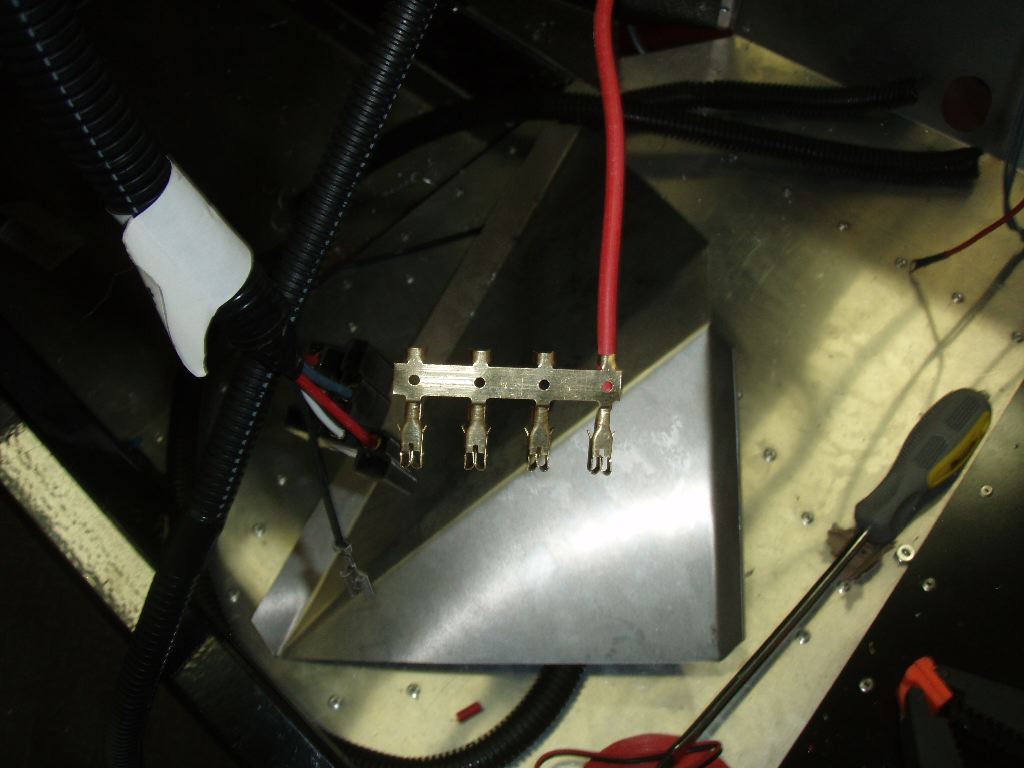
To power the four positions in the fuse block, I used the Ron Francis harness’s alternator feed. Typically it would’ve run from the starter relay to the alternator. I felt, early on, that the line was not safely sized and I needed to run the alternator line to the rear of the car anyway so it was on the battery side of the master power switch. Instead of pulling the entire line out of the harness, I just removed the portion that ran to the alternator and kept that in the dash. This gives me a 10 gauge power feed straight from the main power line in the car. I trimmed it to length and soldered it to the hot side of the fuse block’s terminals.
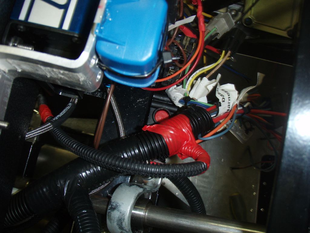
The wire was then bundled up in loom and taped off.
Thats the point at which I stopped — I realized I hadn’t eaten lunch and needed to. I may work some more today and tomorrow on the car, and if so I’ll post another update.
I think a few more weeks and the wiring enough to get the car started should be done, and I can get back to heater plumbing and fuel lines — the two remaining things I’d need to start the car in the early spring.