Yesterday I spent a good bit of the day getting the steering set up, futzing a bit with the alignment on the car and starting to fabricate a tool I could use with my iPhone to do a real alignment on the car. Today I got the suspension and steering totally finished — all the bolts are torqued down and the alignment is done.
The day started off with a trip out to the store to pick up some parts I needed. Once the alignment was done, and I got a few new circuits run to the rear of the car, I was going to get the sheet metal all installed in the car. I needed to buy a few different colors of wire to use, as well as a pair of RCA cables, so I could run a new bundle of wires for the stereo as well as the backup light. I also picked up the parts I needed to rig up an alignment frame around the car. It was a good and productive trip out and by 11 I was back home and ready to start working.
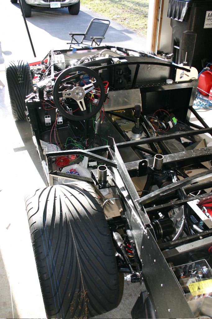
It was a gorgeous spring day with temperatures in the high 50’s — perfect for working on the car with the garage door open.
The first thing I did was tweak the frame I built yesterday to hold the iPhone — I bought some angle brackets, and riveted them between the vertical support and the side arms to hold everything tight.
The goal of the alignment frame was to essentially get two perfectly parallel points of reference along the car, both parallel to each other and parallel to the centerline of the car. There are a lot of different ways people have done that, although most of them I’ve seen have been somewhat imprecise. I decided to buy two lengths of 1″ PVC pipe and to drill 1/2″ holes in it, carefully aligned to bolt into the quick jack mounting points on the chassis.
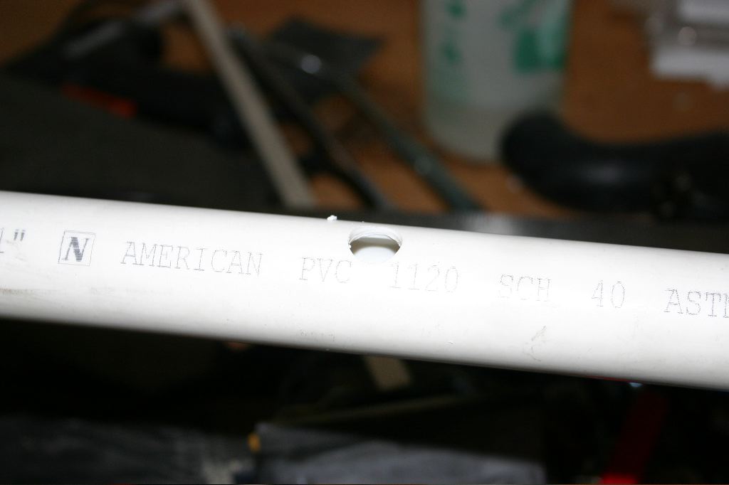
By carefully measuring a given distance (39″ in this case) out from the center point between the mounting bolts, both on the front and the back and drilling small holes there, I’d end up with four holes precisely aligned front to back and 4-5″ beyond the width of the wheels on the car. By tying a string between them, I would establish perfectly parallel lines to align the wheels from.
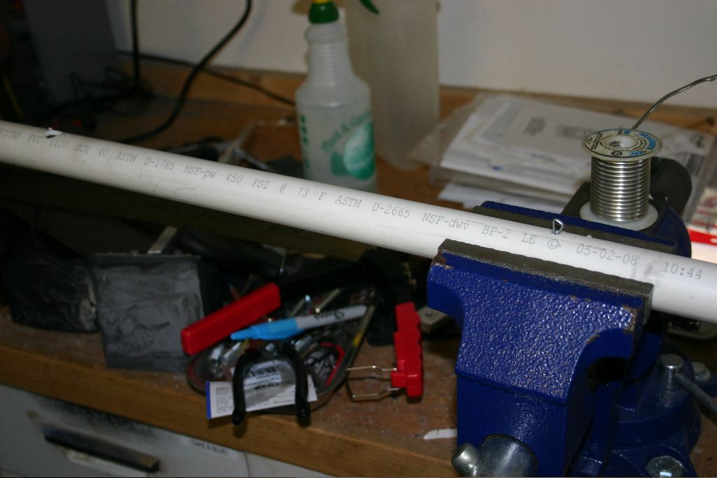
To start off, I carefully measured and drilled the holes in the two 7′ PVC pipes.
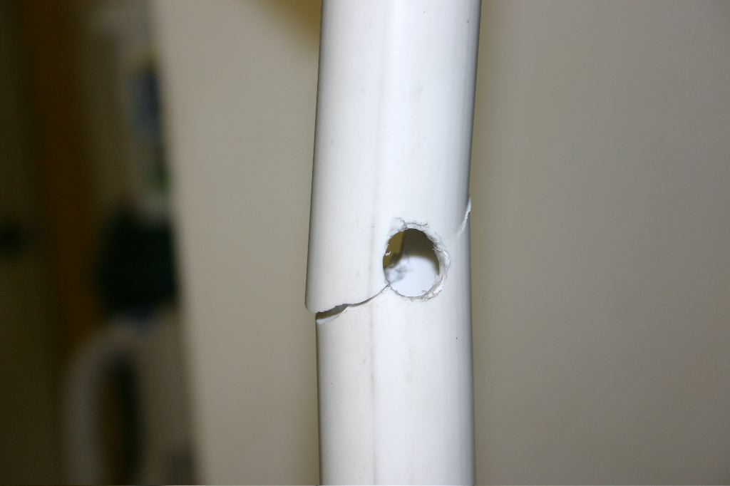
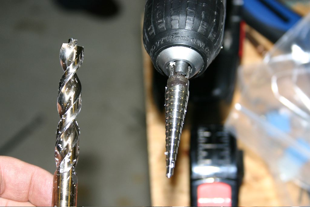
The first pipe I managed to break all the way though. Originally I was using a wood/metal bit (on the left in the photo above), and it just put too much stress on the pipe. The uni-bit drilled the holes less aggressively and worked perfectly. Unfortunately I had to go back out at lunch and buy a third PVC pipe to replace the broken one.
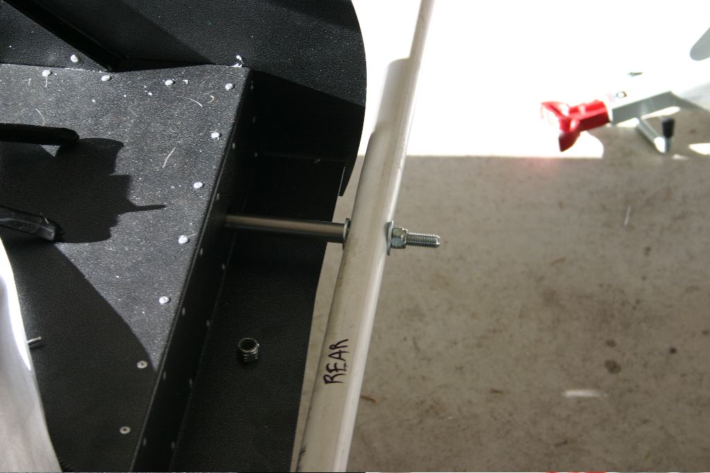
Using the body mounting bolts and spacers, I bolted the pipe to the rear of the car.

The bolts hold the pipe just beyond the end of the car.
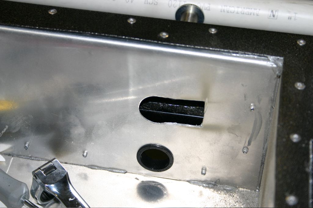
I discovered, as I was putting the bolts in the rear, that the crappy quality of the Dark Water Customs trunk boxes did, in fact, bite me. The holes drilled in it to give access to the bolts were more than an inch off. I had thought, when I first got them, that I’d still be able to make it work. It turned out there was just no way to get the bolts in AND get a wrench on them. Using a cut-off wheel on my dremel, I opened both the top and bottom hole up. I’ll cut a patch panel and rivet it to the back of the trunk box once the body is installed for the last time in the car. Until then I’ll just put some tape over them to keep things from falling through them.
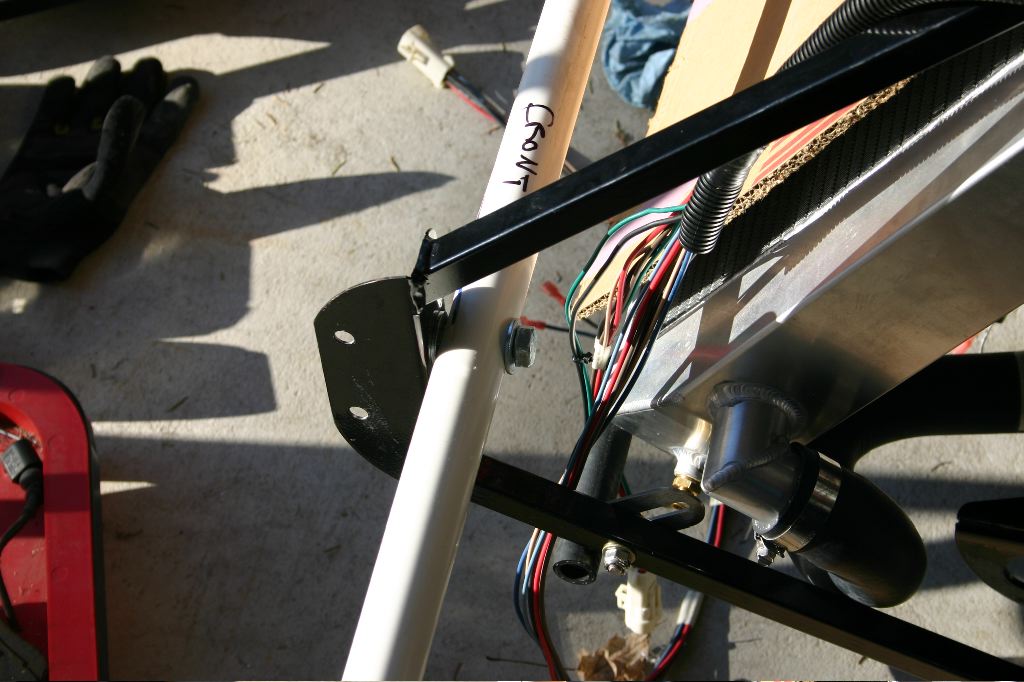
The front bolted on similarly — in this case on the back side of the quick jack mounts. I couldn’t find (if there are any) the spacers for the front, so I couldn’t extend the bolts out and mount them all the way at the front. Once the two pipes were firmly bolted to the car, I ran some twine between the ends of them.
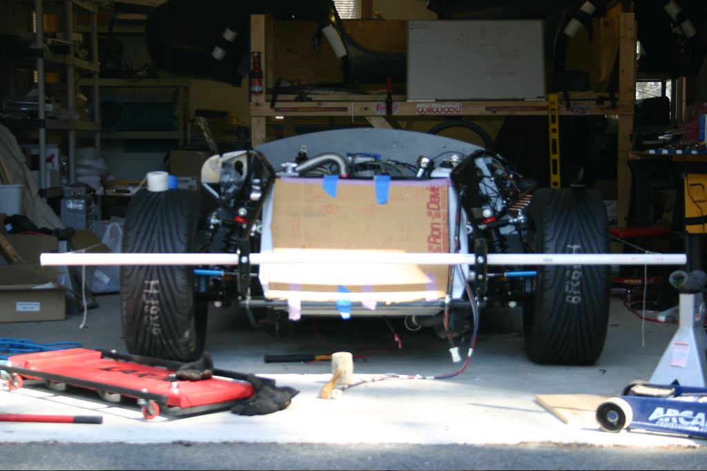
Unfortunately I got caught up in the work and didn’t get any photos of the alignment frame from an angle where the strings could be seen.
Using a ruler, I could then measure the distance from the string to the edges of the wheels on the front and the back. The rear and is one-time adjusted. Once set, it never drifts out of alignment. Unfortunately adjusting it means actually unbolting the control arms, which is both difficult and a matter of trial and error. By some miracle, the toe in the rear (the difference in distance between the front and rear edge of the wheel relative to the center line of the vehicle) was exactly 1/16th of an inch on each side — precisely to spec. Once-in-a-million shot, there.
Using the alignment tool, I could then measure the camber (the angle of the wheel tilting towards or away from the car). To be in alignment, they needed to be tilted 1 degree towards the car.
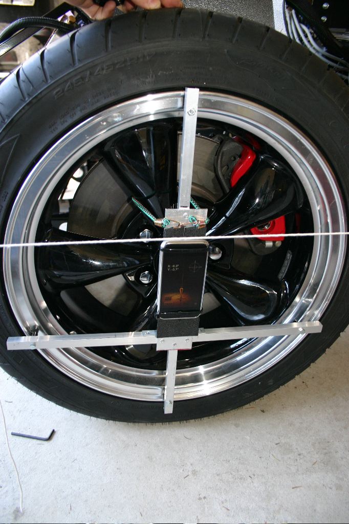
The frame fit nicely against the wheel and was held in place with a small bungie cord.
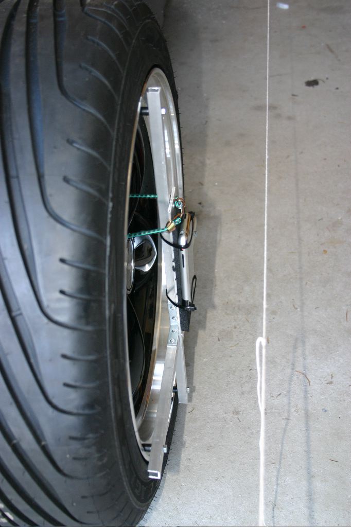
A side view of the rig where the alignment twine can be seen.
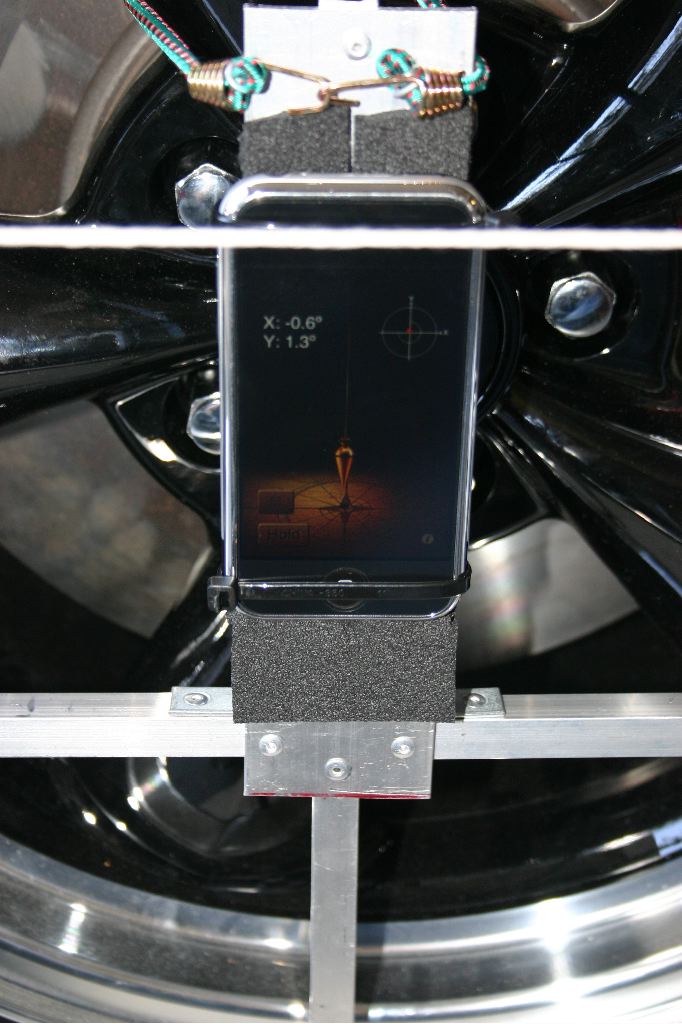
The program, once calibrated, can measure precisely the camber of the rear wheel. It turned out they were right around straight vertical. I debated just leaving it at zero degrees, but eventually decided to unbolt the upper arms and adjust them inwards slightly. Both wheels are at 1 degree and 1/16″ now.
The front was a bigger challenge. Its easier to adjust them — nothing needs to be unbolted, in theory, but there are a lot of adjustment points. The wheels need to have their toe set to 1/16″ as well, but adding to that complexity is the need to do so with the steering wheel still pointing straight up. Adjusting them puts pressure on the steering rack which causes the steering wheel to turn, so its a very iterative process.
On top of toe and camber, in the front you also have to worry about caster — which is the amount the vertical axis of the wheel rotates along the axis of the car as the wheel turns. You want the axis to rotate 3 degrees when the steering wheel turns 15 degrees. Sound complicated? It is — thankfully the rig I built to hold my phone could easily and accurately measure caster as well.
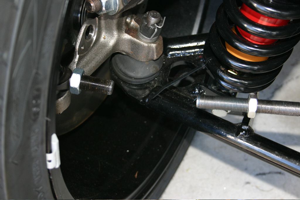
Unfortunately I realized on both sides that when the car was properly aligned, there was almost no threads in the adjustment collar from the tie rod ends (the short part bolted to the wheel in the photo above). Fixing that meant screwing up the alignment again in the front, unbolting the tie rod ends, then more carefully choosing how far to thread each end into the tie rod and ends so that I’d have a half inch or more of threads engaged as it got into alignment. It took a bit of trial and error but I managed to get both sides set up correctly.
Another hour of time was spent getting all the suspension bolts torqued down to spec.
After seven hours of working on it, I wrapped up the day cleaning up some of the tools and having the suspension done. As far as the steering or suspension is concerned, the car is road-worthy now. In reality the rear end is done — with the exception of the couple of wires I need to run.
Tomorrow’s plan is to get the wiring in the chassis done, and get all the sheet metal riveted to the car, both in the cockpit and in the trunk. In the evening, when I can get some help, I’ll get the body mounted to the car so I can do all the body-related wiring on Tuesday (headlights, taillights, turn signals, hazards, horn and wipers).
Unfortunately the weather isn’t supposed to be as nice, but that’s what a garage door and heater is for.