Another busy day has come and gone. Once again I got a bunch of things done, and stumbled on a few problems. Today’s focus was on the dash wiring primarily, and when I couldn’t take standing at the work table any more, I’d take a break and work on other stuff. The dash isn’t done yet — although its mostly done — and I haven’t touched the wiring behind the dash yet, but I’ve got sketches of most of the schematics done.
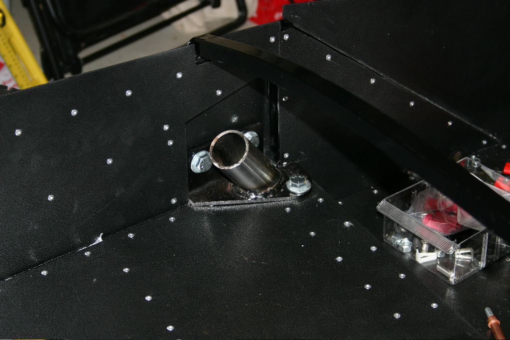
First off, I wanted to post a photo of the passenger rollbar mount. I shot it last night after I’d posted yesterday’s update.
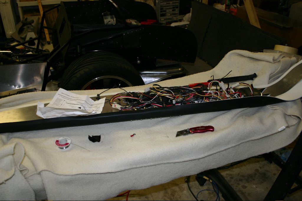
This morning, after doing some cleaning in the garage, I made room on the work table to lay a blanket down and get the dashboard back out of the house. I have four tasks to undertake on it, of which I addressed two today:
- Wire up the gauge power and lighting
- Wire up the switch panel and LEDs
- Wire up turn signal / high beam lights
- Wire up sensors to the gauges
The first two are the parts I worked on today. A big part of the morning was spent jotting down schematics on the whiteboard working out the best way to get everything wired up. The Ron Francis harness typically has the turn signals on the dash and the lights not on the dash. Mine are the other way around, which means most, if not really all, of the existing wiring harness wasn’t usable as is. Thankfully because I can pop terminals out of the Delphi connectors and reorganize them, I can reuse a lot of the wiring even if I have to route it to different places.
As I was looking at how I’d wire up the dashboard, I decided the first thing to do was to pull out the switches and deal with the four LED indicators. In theory that meant wiring all their common grounds together and leaving the power feeds separate, to be wired into the business side of the switches.
This turned out to be quite a task — the LEDs are tiny, and getting wires securely soldered to them was no easy task, and the LEDs are fairly close together. When I’d gotten part of it done, I discovered the LED holders in the switch panel weren’t holding them securely. A lot of them mount the LED from in front, so the connection on the back holds them in. With these, the leads basically pushed through a rubber plug with two holes in it and the plug was just friction-fit into the holder. They just wouldn’t stay.
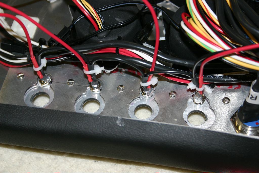
After spending some time fooling around with them, I decided to use my hot glue gun to first set the leads in a bead of glue to insulate them, then to glue them into the holders. While it will be difficult to ever get them back out again, they are definitely secured well. In the photo above, the common ground (black) can be seen bridging the four LEDs, the red wires are the hot wires.
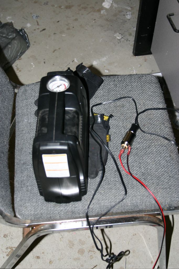
For testing the dash outside of the car, I used a portable jump-starter and air compressor which has a built in 12v battery to make sure the switches and LEDs were wired up correctly.
The first switch I wired was the headlight switch. This switch is a standard on-off-on toggle switch. When the switch is in the center, the lights are off. With the switch down, the dash and parking lights are on, and with the switch up the dash, parking and headlights are on. Most headlight switches are built to do things like turn on three different circuits at the appropriate times. Because this is a standard toggle switch, I had to also wire a diode into the circuit to ensure that when the parking lights were on the headlights weren’t, but when the headlights are, power is also fed to the parking light circuit. The dash lighting is tapped off the parking light side of the switch, as is the “on” LED above the switch. The outputs are used to toggle relays, so very little power is in these circuits.
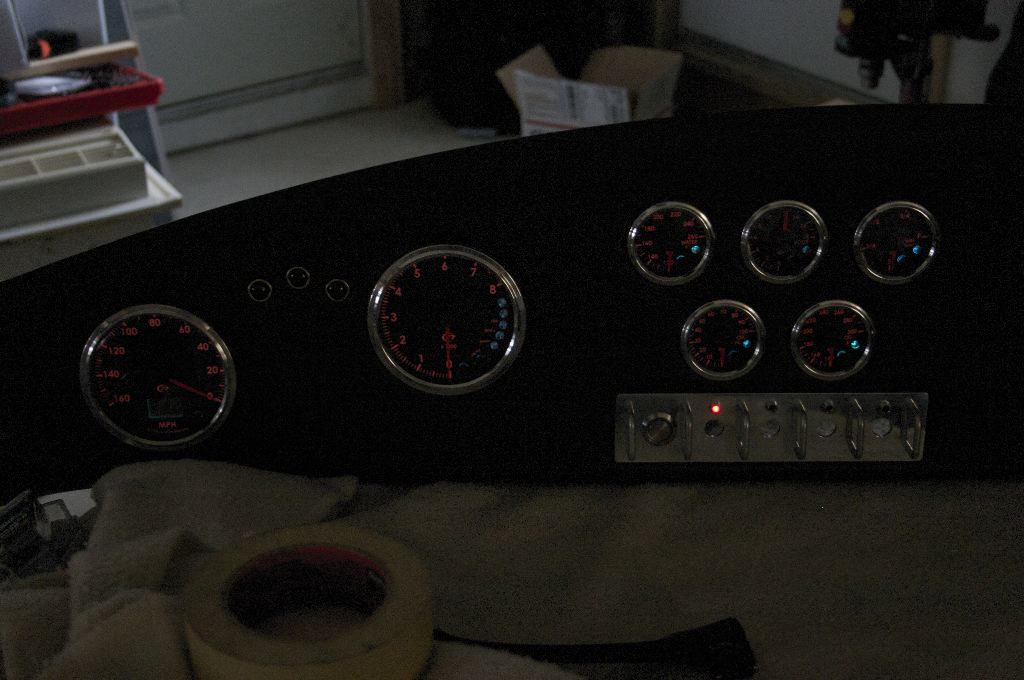
A test of the headlight switch shows the dash illuminated, with the Lights LED lit. The switch is behind the dash. (Also, in a past post I mentioned the speedometer needle was stuck at 20mph and I was concerned the gauge might be broken — as soon as I gave the gauges power, they calibrated themselves and it reset back to zero correctly.)
The next switch in line is the hazard switch. This is a single off-on toggle switch. It takes a power feed from the hazard lights flasher circuit in the main fuse panel and feeds power into the left and right turn signal circuits. Of course, my turn signal circuits aren’t in the dash, so I can’t wire it up the way it normally is in the dash. Also, they typically use a switch that can toggle two separate circuits, where mine can do just one. I could’ve bought another switch, but the store I bought these from are an hour drive away.
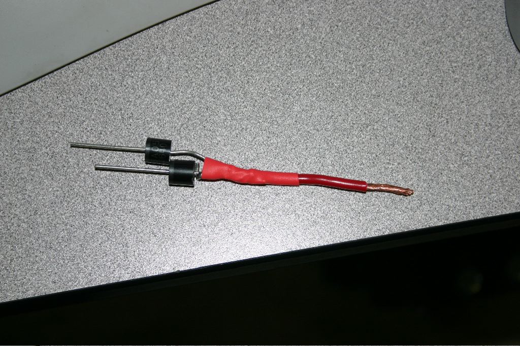
To solve this problem, I made an inline diode cluster. The output of the hazards switch goes to the dash LED as well as into the diode cluster. Its job is to deliver power from the hazard circuit into the left and right turn signal circuits without providing a short circuit for power to get between them when the turn signals are on. Without this, turning on my turn signal would cause both sides to flash. The photo above is partially assembled — the final unit is fully enclosed in heat shrink and is wired inline in the harness.
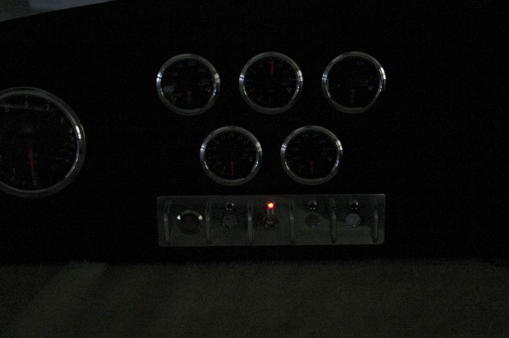
This is another test of the LEDs — in this case the LED and switch for the hazards. When wired up to the hazards circuit, the dash light will flash along with the turn signals.
The third and fourth swiches are for windshield wipers and a garage door opener. They are identically wired — two wires, power in and power out. The wipers typically use a two-way switch for high and low speed, but I don’t intend to drive in the rain anyway so a single speed is fine. (Mostly because I didn’t realize the FFR wipers were dual speed when I bought the switches…)
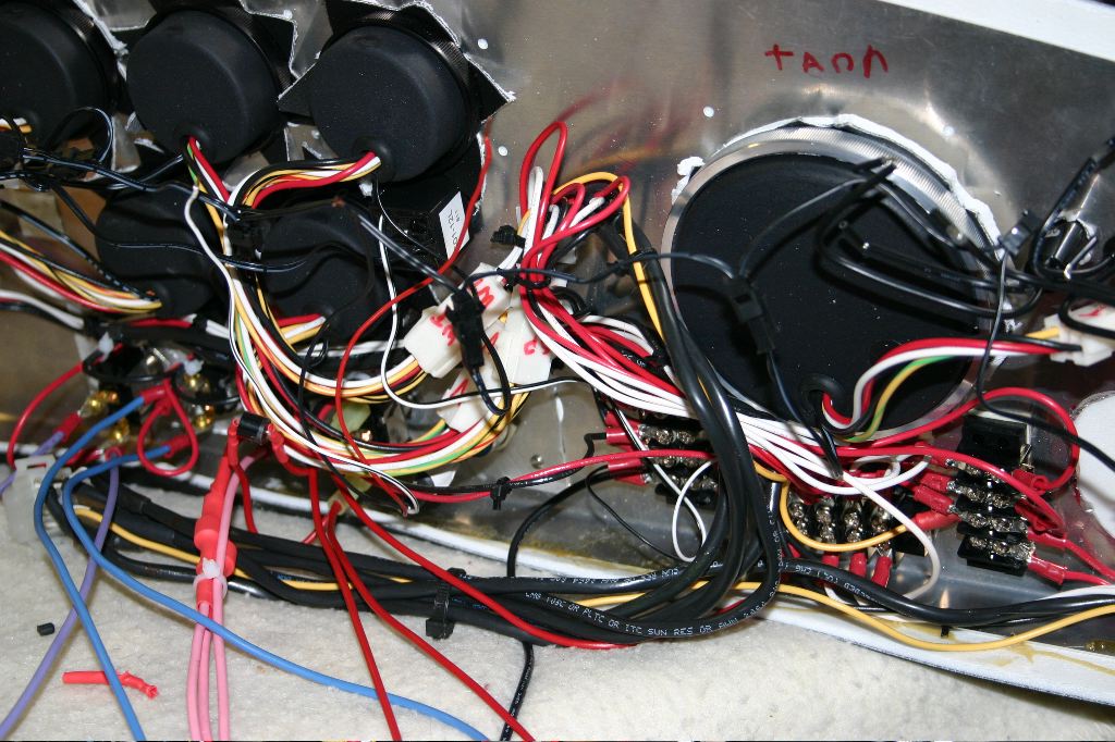
Unfortunately the dash wiring has really gotten messy. I could clean a lot of this up, but I didn’t want to replace or splice any of the dash gauge wiring, so there is a LOT of extra wire behind the dash. Thankfully there is a lot of room back there because of the FFMetal firewall.
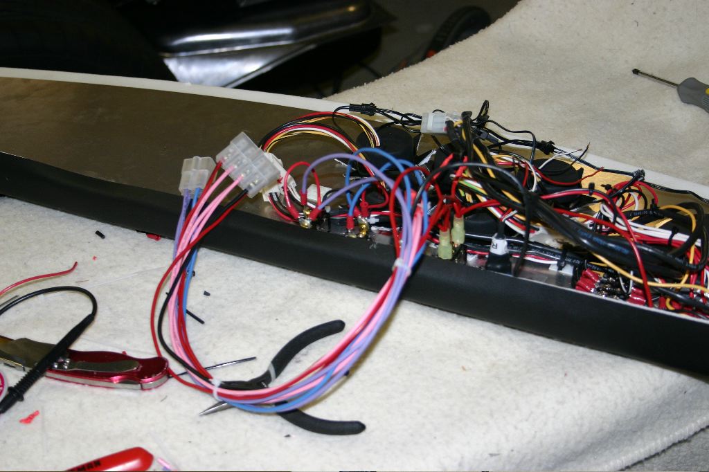
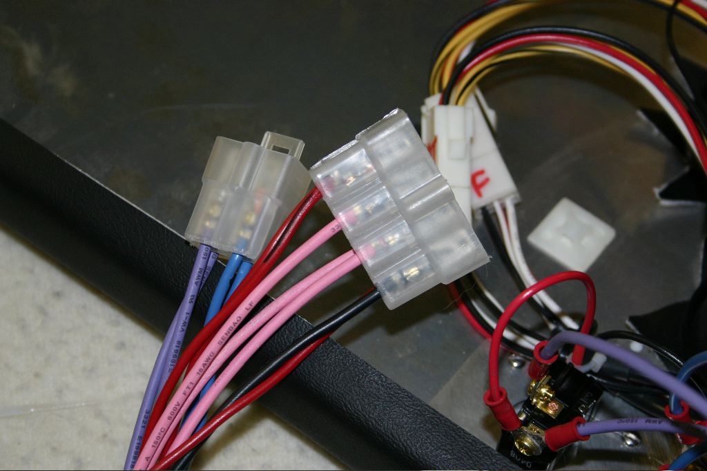
All of the switch wiring got bundled up into a big bundle. There are 11 wires total. To connect them to the car, I used a male 8-position Delphi connector and a 4-position male connector. The wiring in the car is female, so a lot of the existing wires in the Ron Francis harness I can just relocate into the correct position for these connectors.
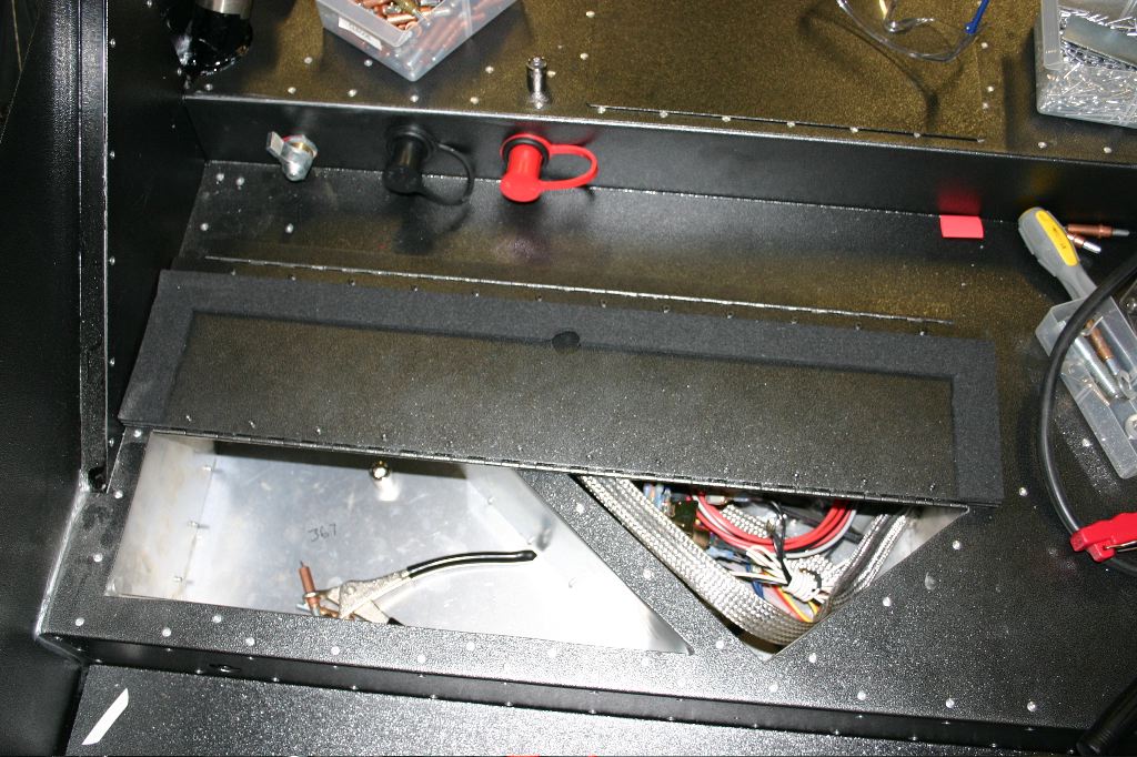
Another thing I tacked, mostly because it was a quick an easy thing to do (I thought) was the hinged cover for the trunk boxes. The cover doesn’t fit well (which shouldn’t be a shocker, since nothing fit right with the boxes!). Because it was pop-riveted, the underside won’t sit flat against anything — the back side of the rivets hold it up. After a bit of brainstorming I decided to use some 1″ closed foam tape to line the edges of it — it both seals it better and raises it up an eight of an inch or so, so the rivets aren’t getting in the way.
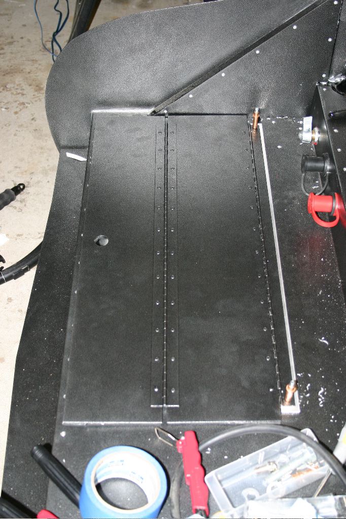
The hinge, then, was too high to rivet to the trunk floor. To raise it up, I used a 24.5″ length of 1″x.125″ aluminum stock, drilled through both and then riveted it to the floor. The aluminum is basically the same thickness as the foam, so everything is solid and level.
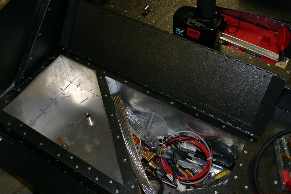

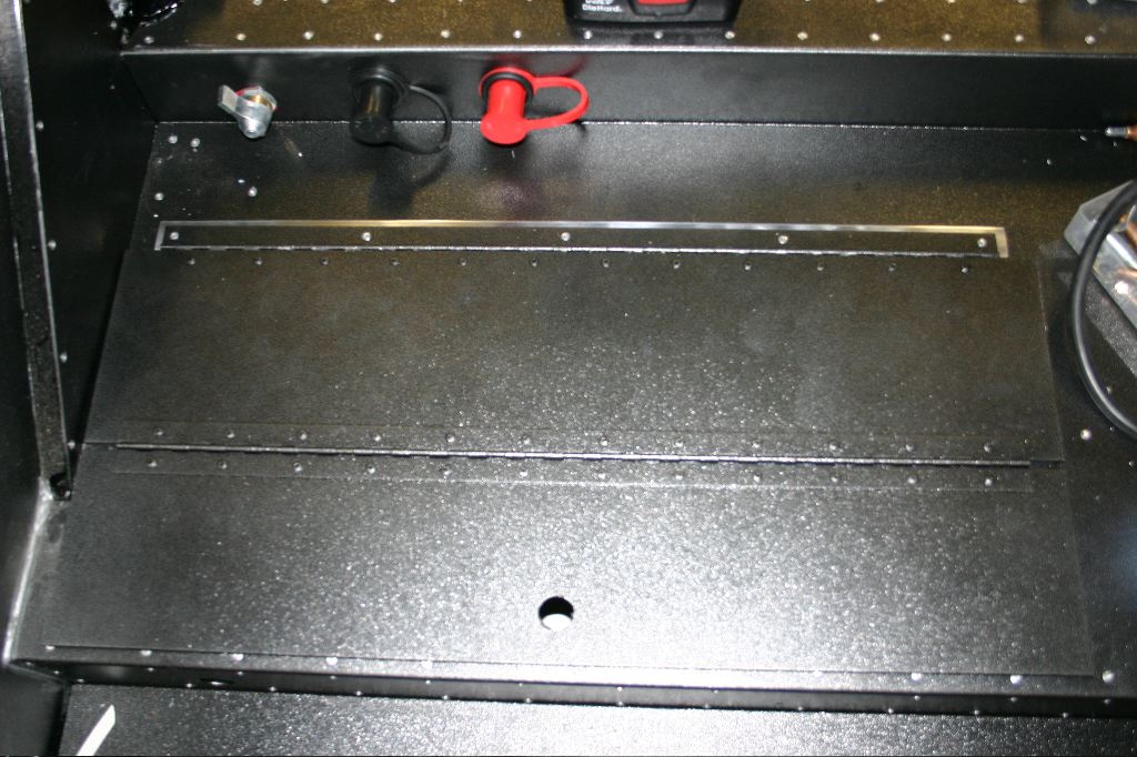
To dress it up a bit, I left a quarter inch reveal around the hinge, and spent some time wet sanding and buffing and polishing the aluminum so its got the same polished texture as the switch panel in the dash.
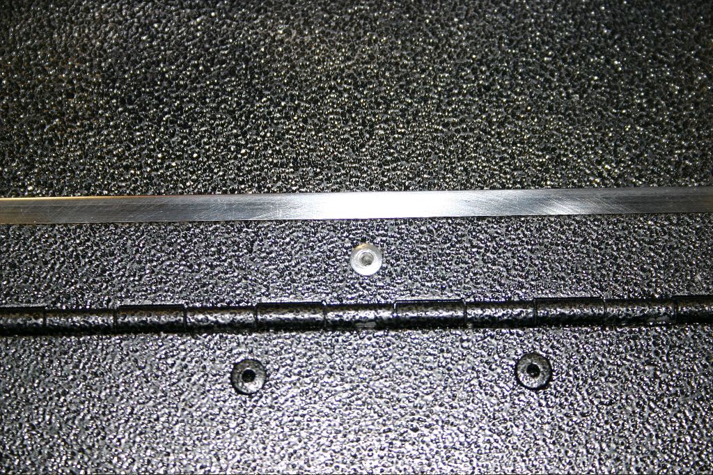
The photos don’t do it justice, but it really does look nice.
A third thing I started working on today was the sheet metal in the cockpit. I drilled the majority of the rear panel, although I discovered I missed drilling any holes in the panel into the steel crossmember above where the seatbelts pass though. Garage gnomes seem to have swiped my center punch, so I didn’t tackle that this evening.
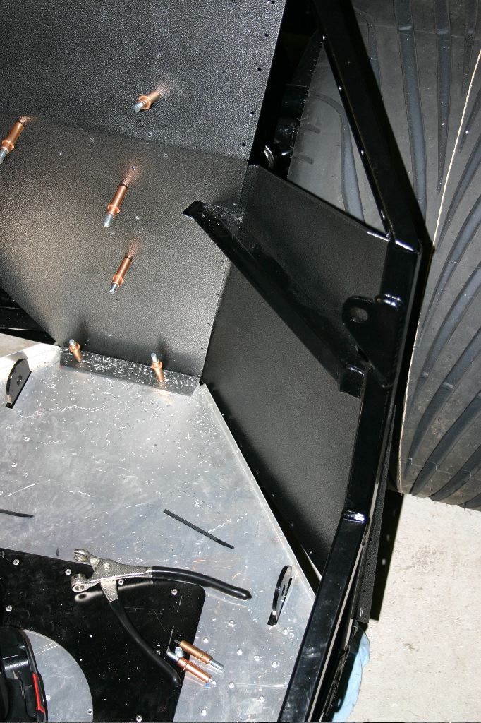
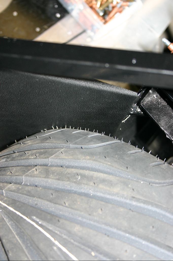
Unfortunately I also discovered that the wheels and tires don’t fit with the lower corner panels in place. I can’t even get them on with the wheels mounted. This is a major problem, and I’m unsure yet how I’m going to address it. The options I think I have right now are:
- Attempt to adjust the IRS mount points to move the wheel back a quarter or half an inch. (Might not be enough anyway)
- Cut a hole in the panel, patch it with something inset a bit more to make a bit more room.
- Replace the panel entirely with something that mounts on the inside of the 3/4″ steel support (visible in the first photo above…) — I don’t have a metal brake though, so this likely isn’t doable.
- Buy half or three quarter inch wheel spacers and longer bolts — basically move the wheels out a bit using a metal spacer against the hub. I need to get the body on to see if I have room in the wheel wells to push them out farther.
- Buy new tires. These were over $400 a piece, not a good option.
- But new wheels. These were $400 total, definitely a better option that replacing the two rear tires.
I have no idea at this point what I’m going to do. I need to finish the wiring and I’ll deal with the tire issue once I have the body on the car.
Tomorrow’s plan:
- Finish the dash wiring
- Finish the wiring behind the dash
- Figure out where to mount the horn
- Deal with dash gauge sensor wiring
That’ll leave Thursday for dealing with this wheel/tire problem and light wiring (headlights, tail lights, etc), and Friday to deal with engine wiring. Saturday, if I’m not totally burnt out on this work week, will be for ignition wiring and installing the new distributor.