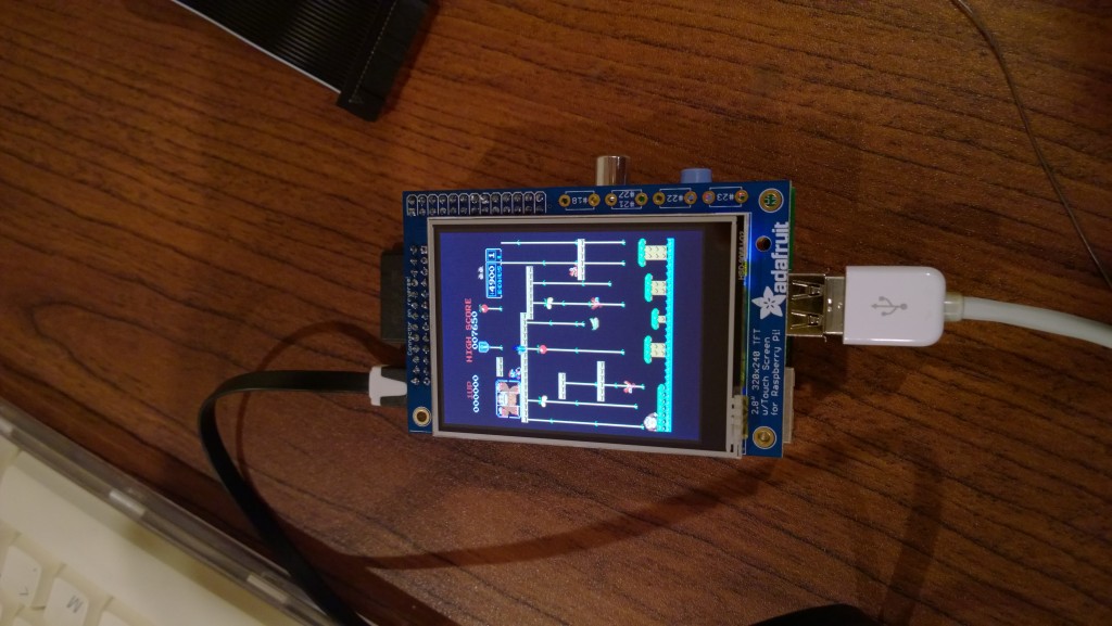
 Last night the bits and pieces showed up from Adafruit for the Cupcade, so I sat down and started assembling it. Its not particularly complicated to put together and its VERY well documented on their website, but there’s a lot of fiddly soldering, made trickier by my not being able to find my low-power iron and having to use a way-too-beefy 40 watt one.
But first things first, its important to set up a good work area.
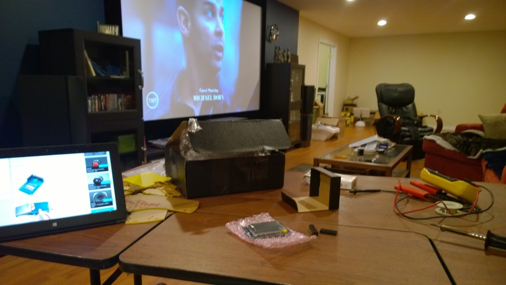
An old computer desk set up on the side of the home theater meant I could watch TV while working on it. I have no idea what that was when I took the photo, but I eventually ended up watching Aliens. What does that have to do with assembling the Cupcade? Nothing, except it was awesome.
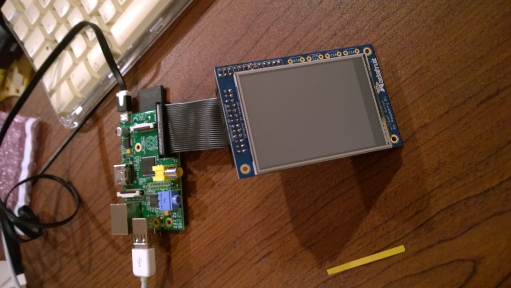
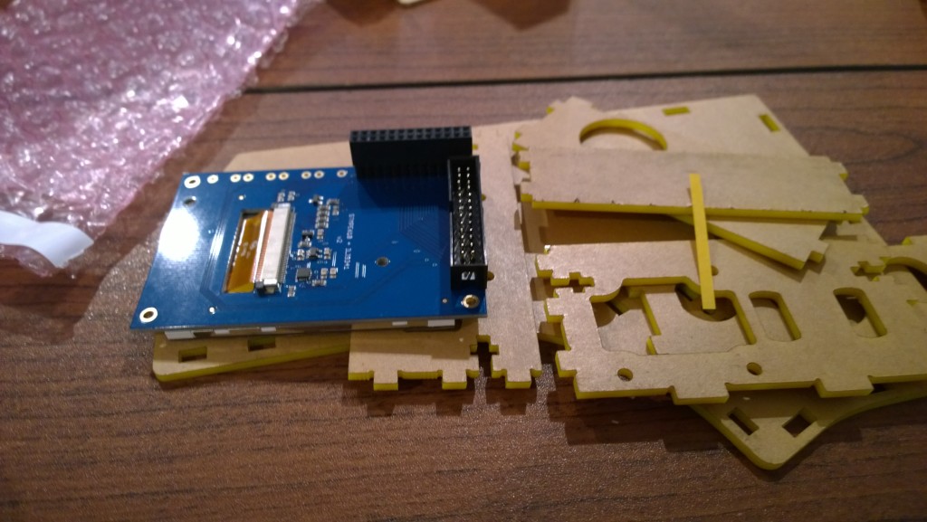 After digging out all the parts, the first step was having to solder two connectors onto the back of the LCD controller board. These are basically pass-throughs for the GPIO headers on the Raspberry Pi. The LCD controller hooks into it, as does the board with the button/joystick encoder.
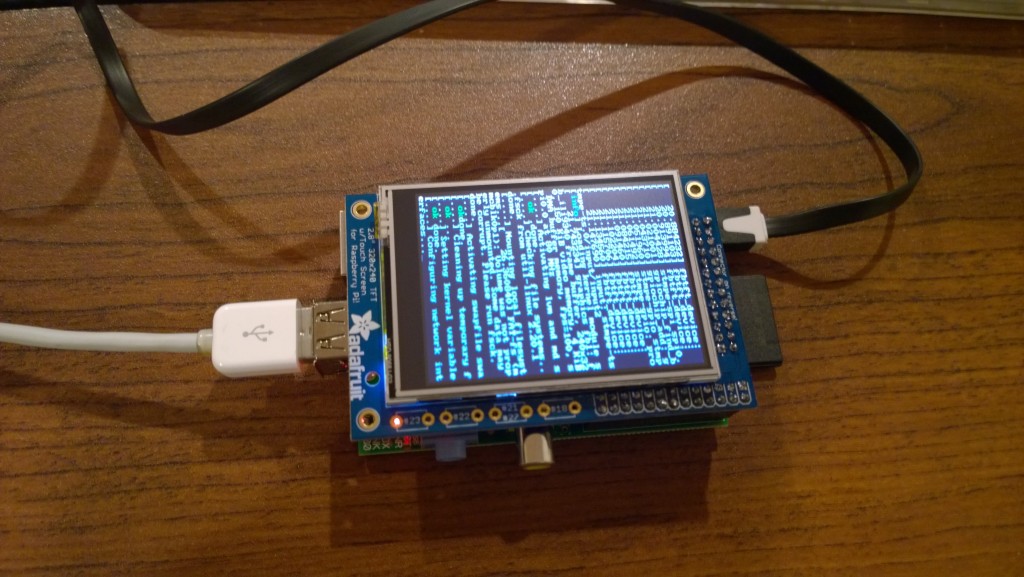 The display board is set up so you can plug it straight into the Pi. The Cupcade doesn’t use it that way, but the instructions suggests doing a LOT of testing in each step. I plugged in a keyboard and plugged the power into my tablet, and it booted right up into Linux. The screen is apparently a touchscreen, which is interesting for future projects, but MAME doesn’t use it. Once the working of the screen was verified, I had to take it all apart and keep going with the soldering.
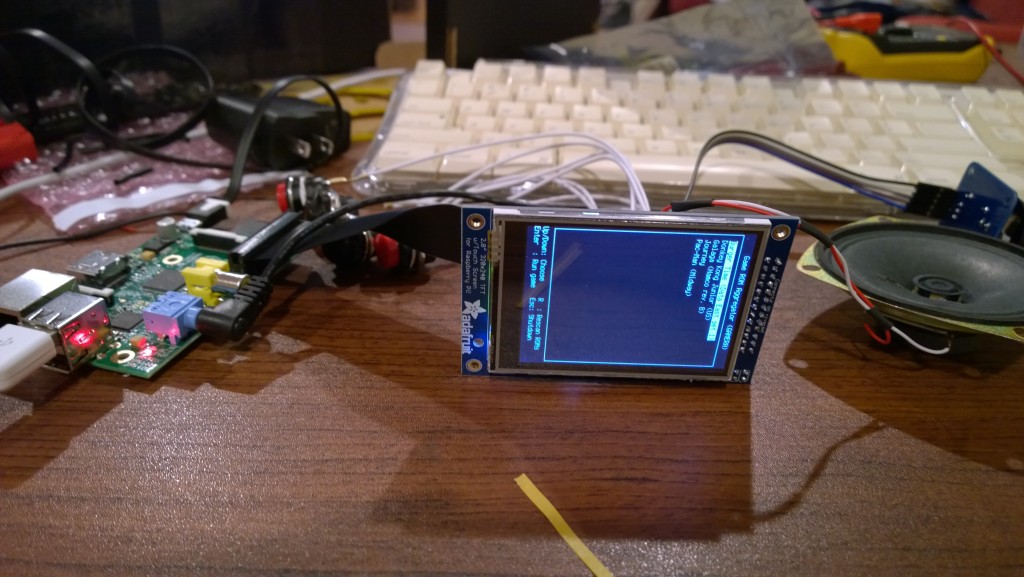
But first, I had to fire up MAME and see it working. It did! It played well using the USB keyboard.
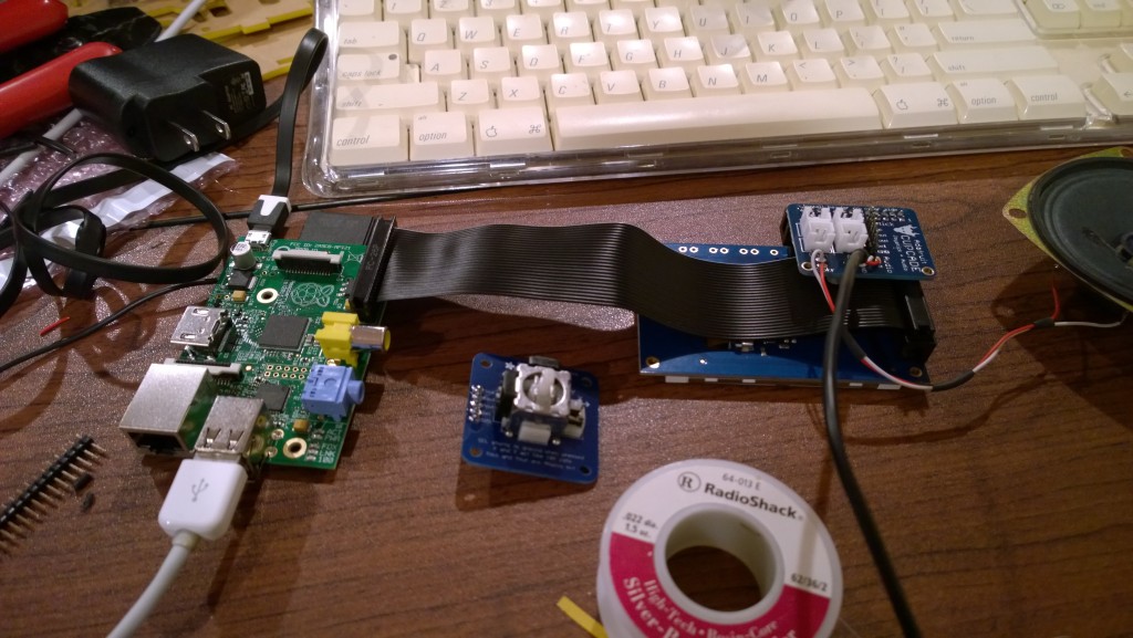
I also had to test with the ribbon cable. Booted up just fine with it in place, too.
A lot more soldering later, and I had the interface board for the buttons and joystick together, as well as the joystick controller board. The interface board is plugged into the GPIO header on the back of the screen in the upper right. The joystick connects to a five pin header, and the buttons plug into the four two-pin sockets. The board also has a small audio amplifier on it, which connects between the headphone jack on the Pi and the speaker.
With everything plugged in, the last thing was testing all the buttons, the joystick and everything else to ensure it was still working. I had a small short in the speaker connection, but that was an easy fix.
A quick video of testing out the joystick.
The next step is to paint the acrylic panels (which, for some reason, are bright yellow) black. Tonight I’ll finish assembling it.
